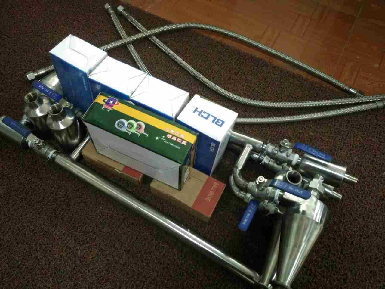
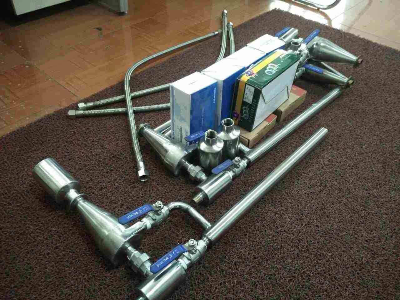
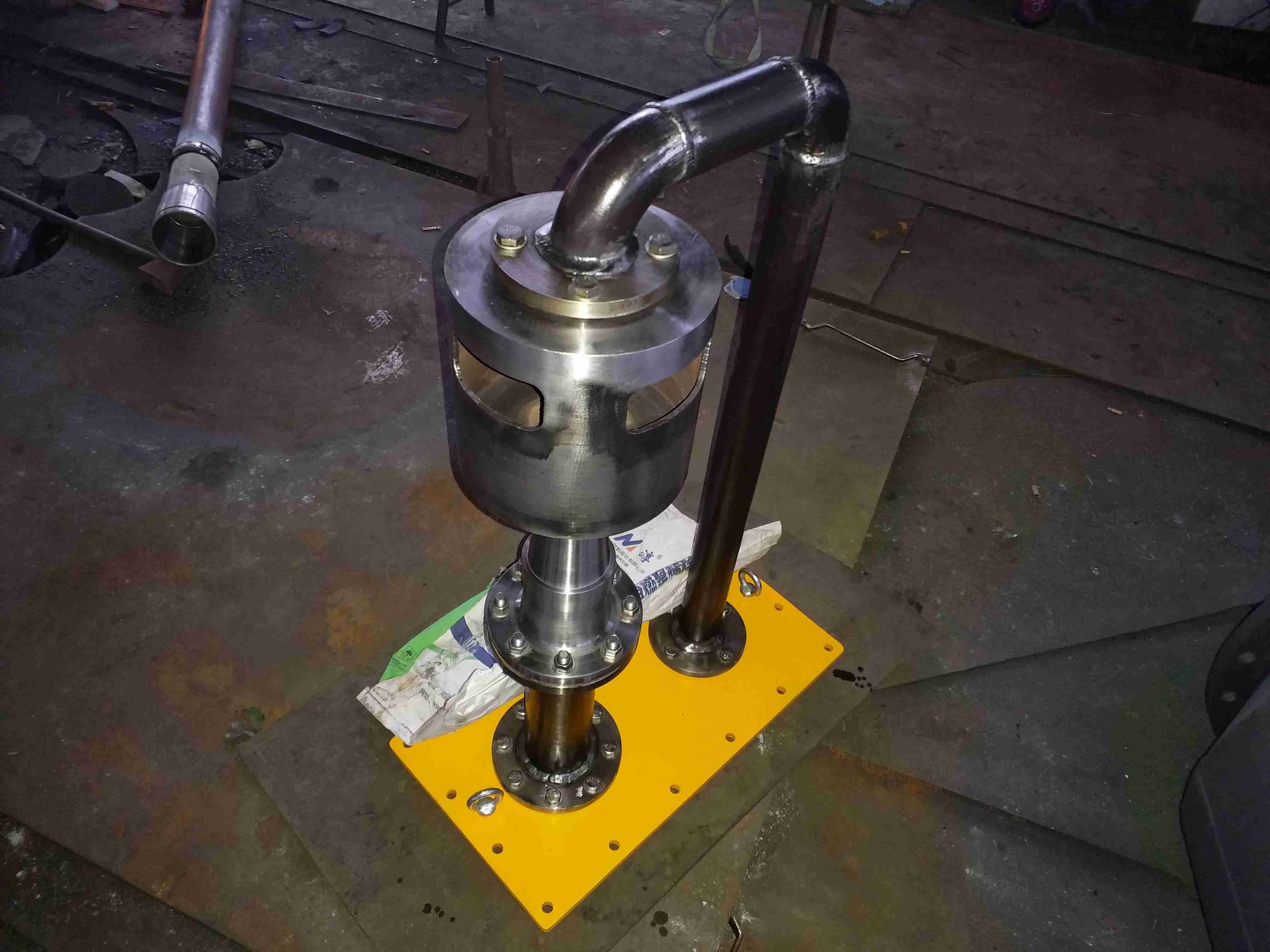
Introduction to water collector:
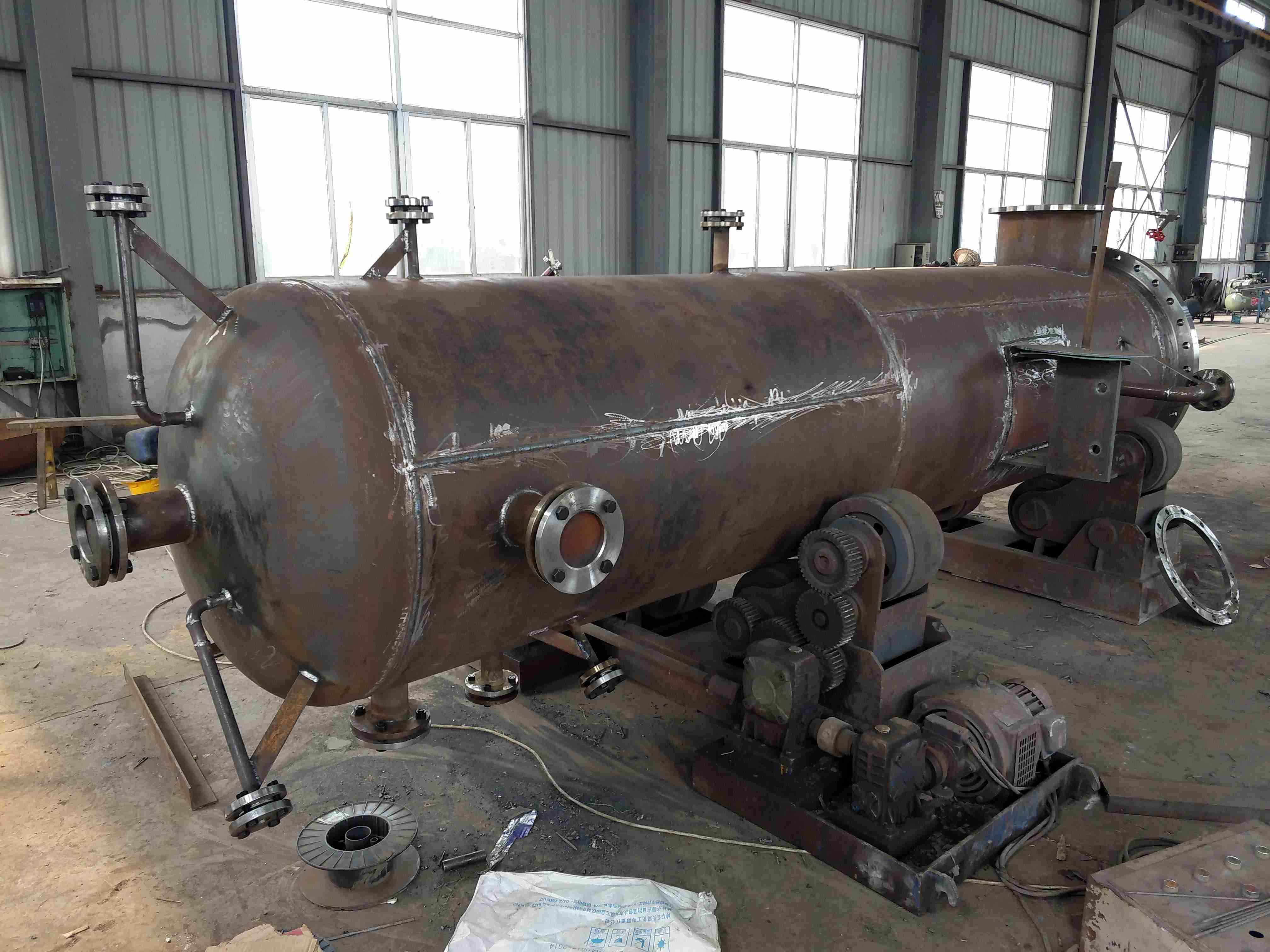
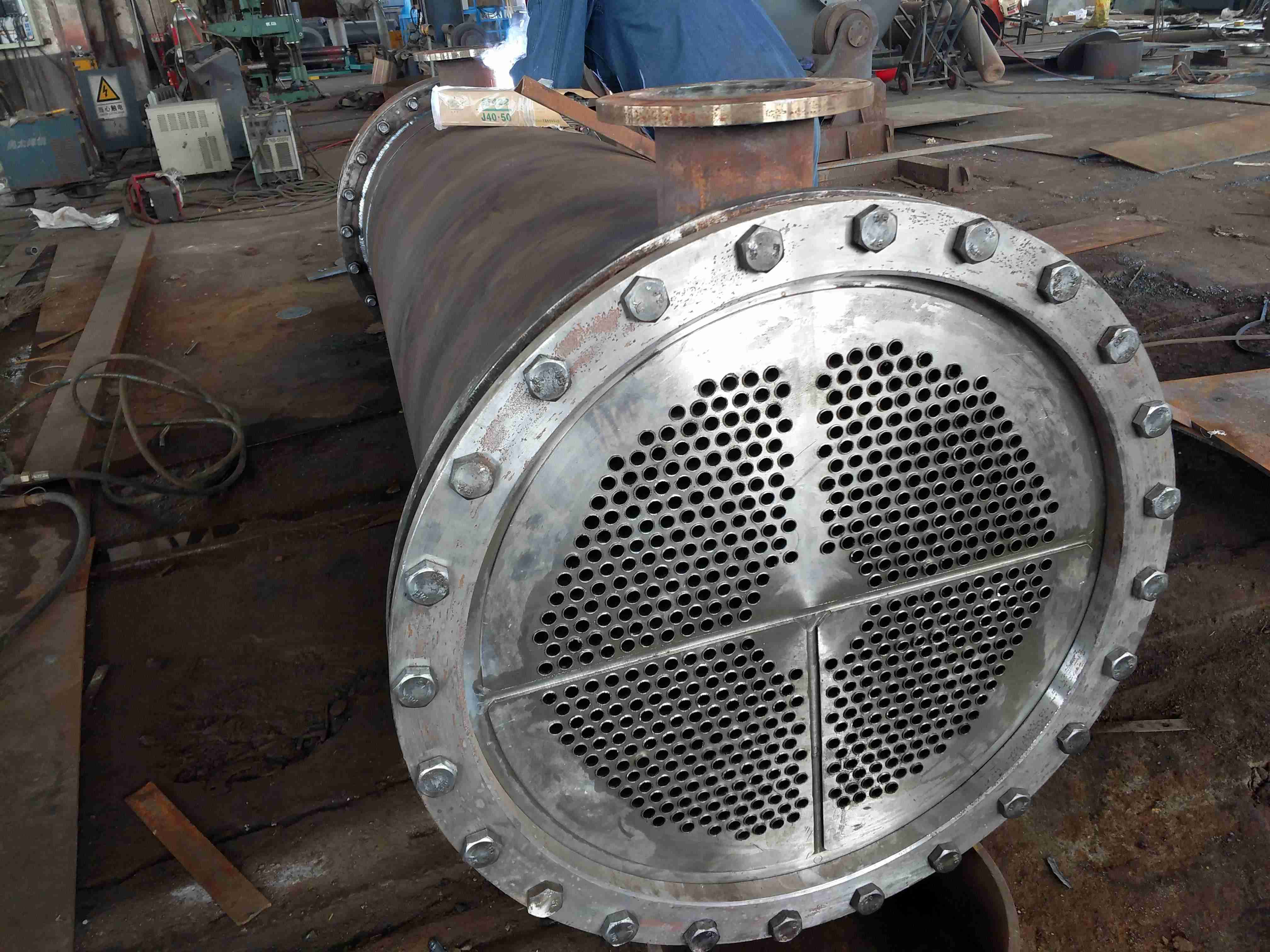
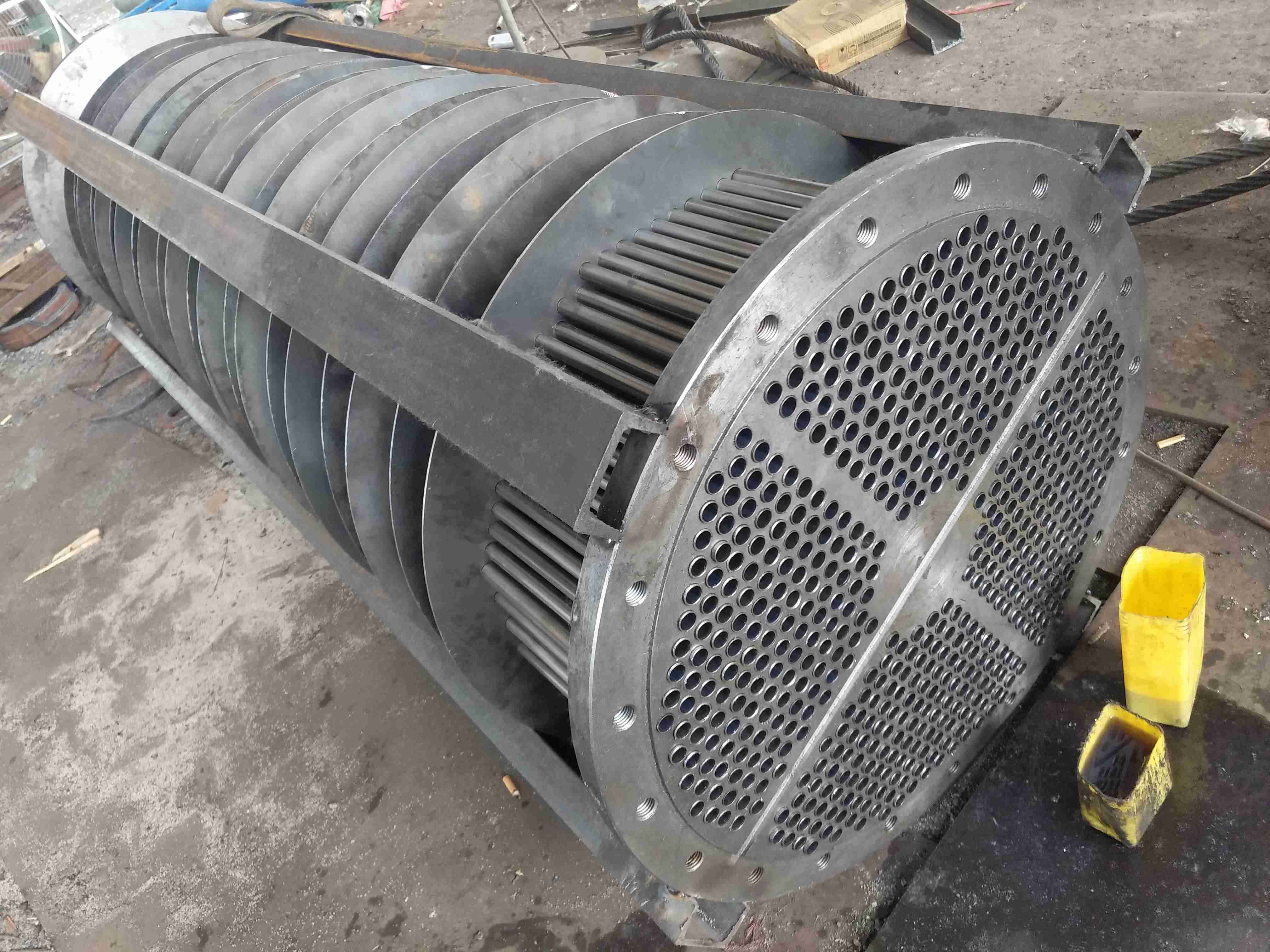
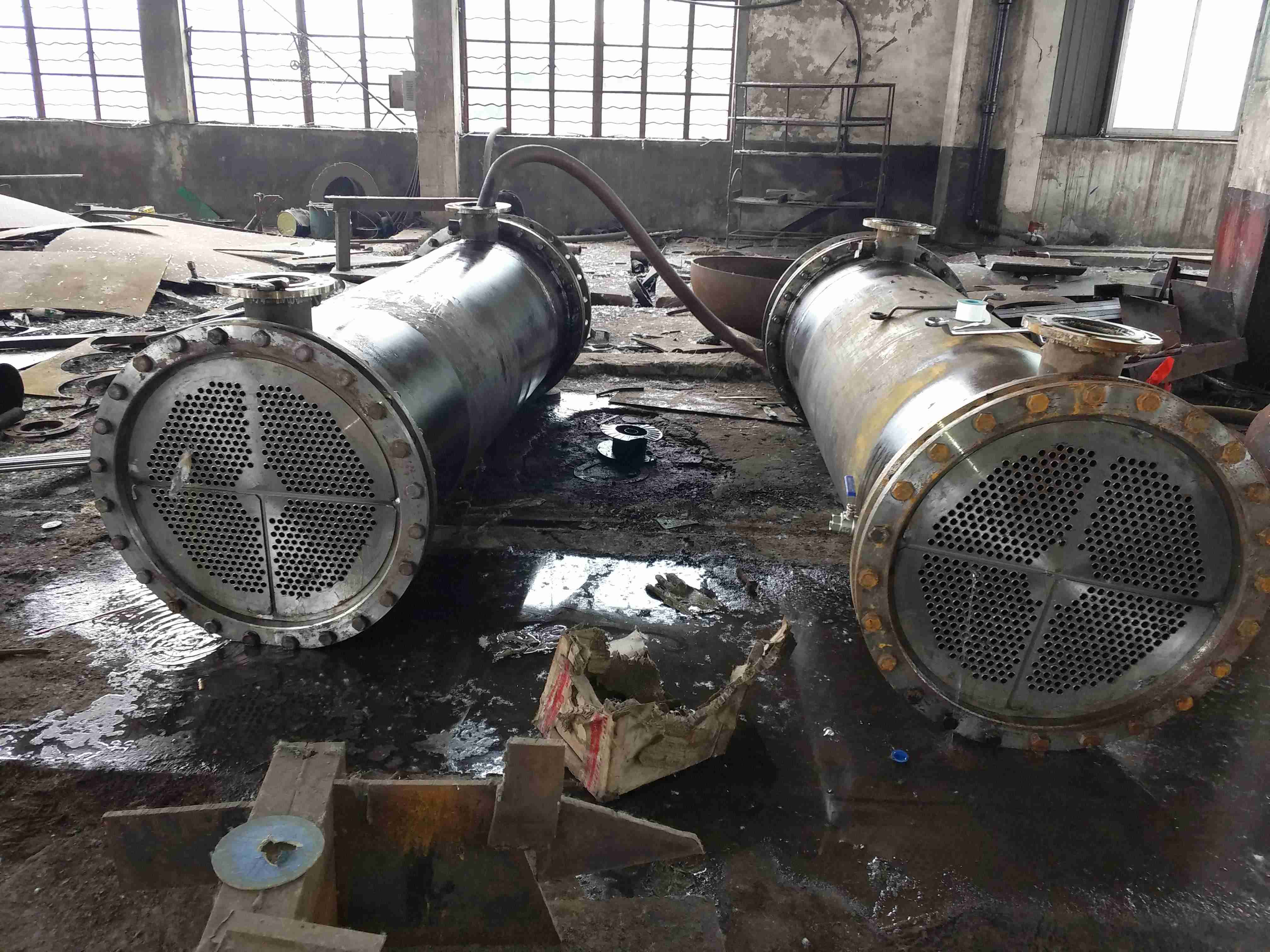
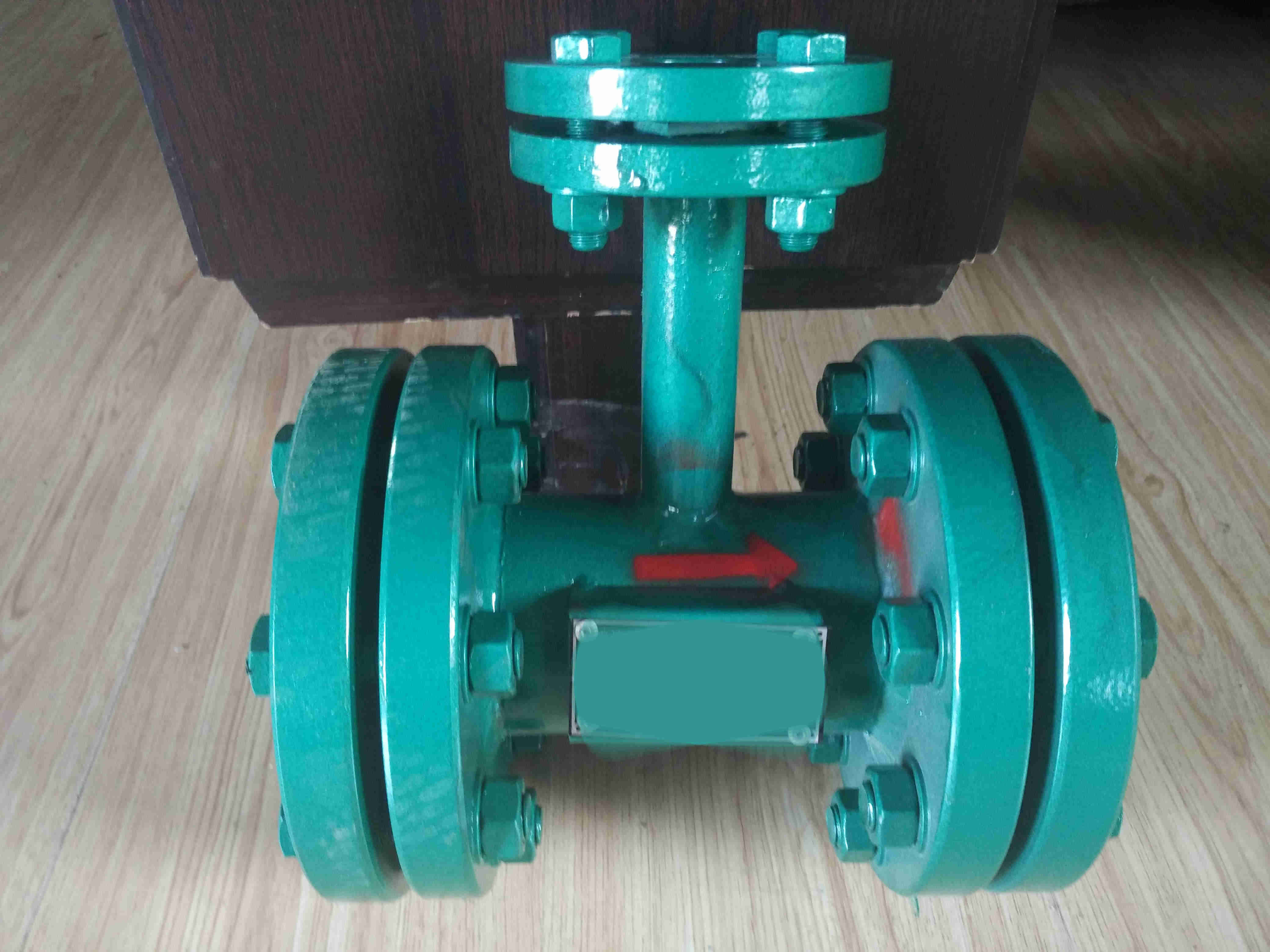
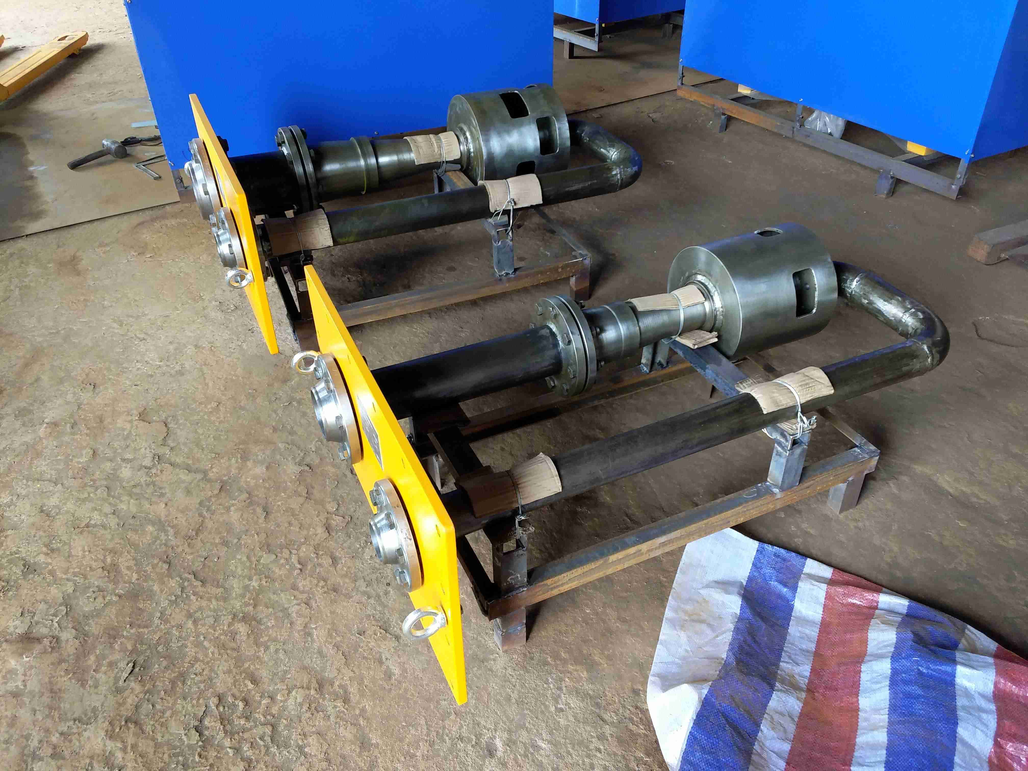
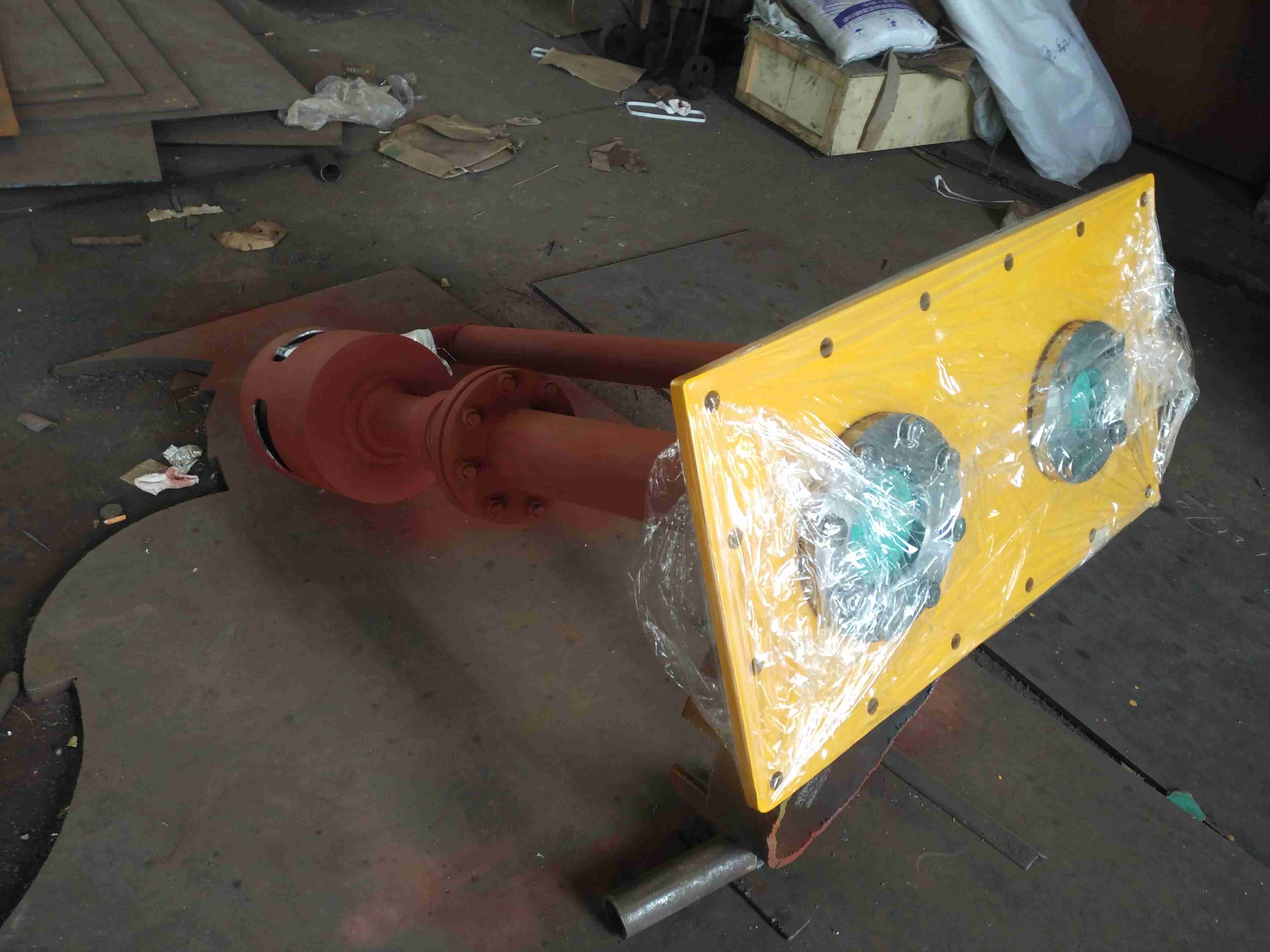
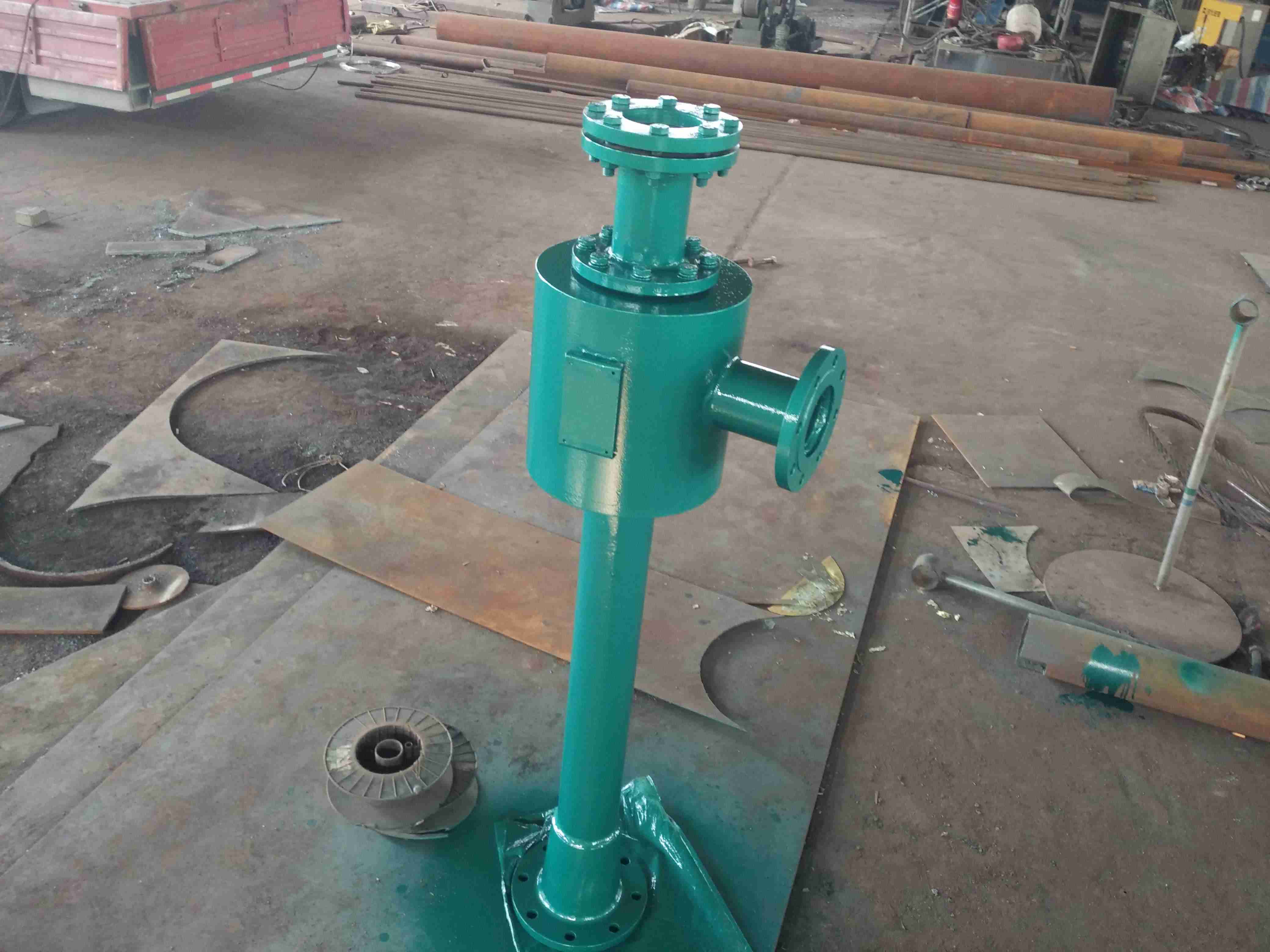
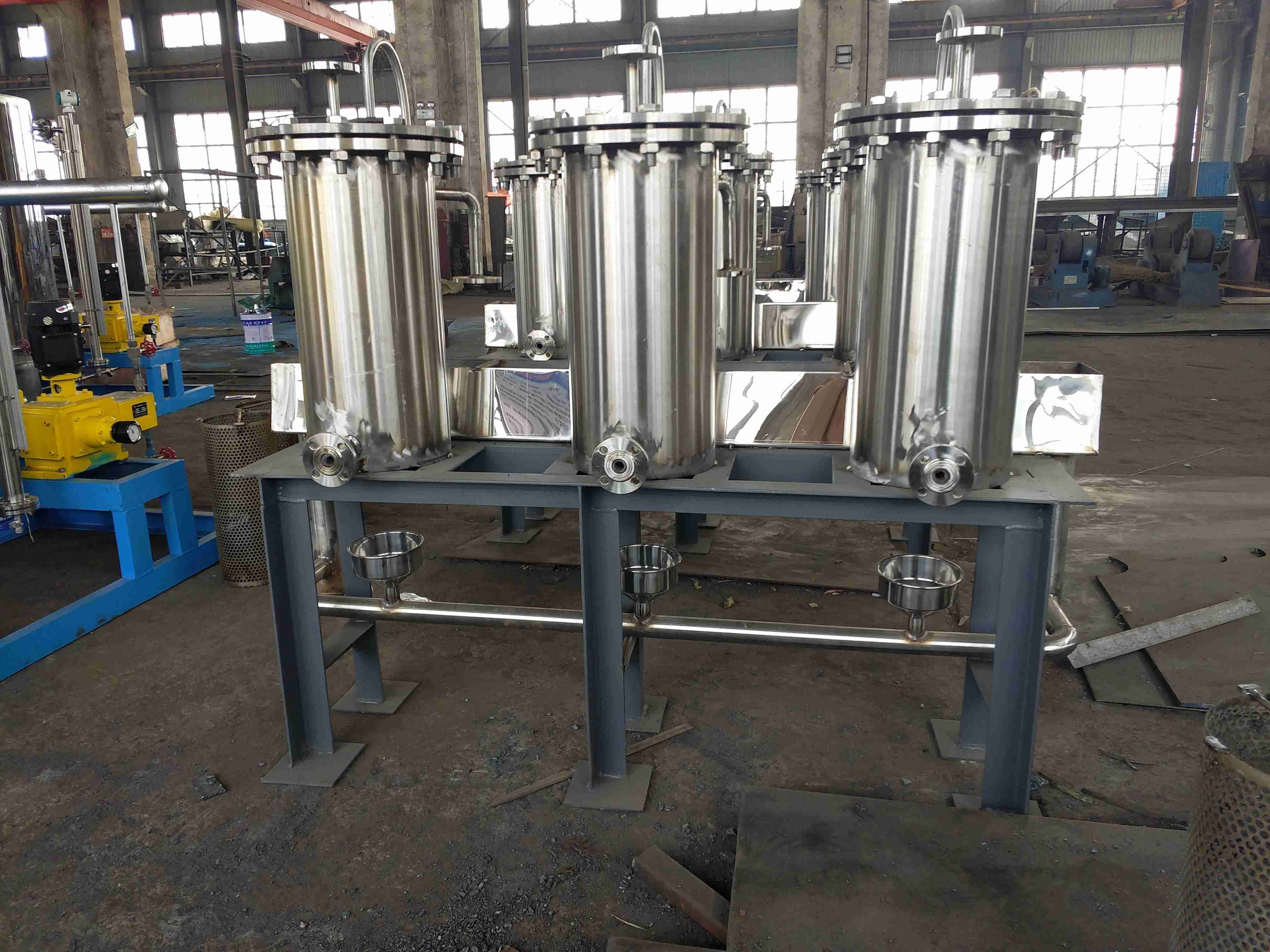
A water collector, also known as a separate water collector, is a water flow distribution and concentration device composed of a collector and a water distributor. A water distributor is a device that disperses the incoming water into several output channels, while a water collector is a device that gathers the incoming water into several output channels. The structure is composed of a main pipe, branch pipes, sewage outlets, exhaust outlets, pressure gauges, thermometers, etc., and a cylinder with a larger diameter is equipped with a manhole or handhole. The material is made of carbon steel plate or welded steel pipes, which can withstand a certain pressure. It belongs to the pressure vessel industry manufacturing, and the outer surface is treated with anti-corrosion or insulation. The cylinder of the water collector is connected to an inlet and outlet pipe as needed, which can collect or divert water from various channels. The cylinder is equipped with a pressure gauge or thermometer, which can facilitate the observation of the water flow status inside the cylinder. The lower end of the cylinder is equipped with a drainage outlet, which is used for the discharge of sewage during the cleaning of the cylinder. Its models range from DN2000 to DN1500. It allocates the flow of water from the main pipeline as needed, ensuring that the flow of branch circuits in each region meets the load requirements. At the same time, it also collects the water flow from each branch circuit and inputs it back into the main pipeline for circulating operation. The reuse of its return water can achieve energy-saving results and simultaneously meet the needs of heating and cooling. It is applied in boilers, central air conditioning, industrial circulating cooling water systems, and hot water systems. It is different from other air conditioning systems such as heat exchange units and vacuum degassers, and the water collector is mainly used in water systems.
Technical standards for water collectors:
1. Strictly follow the design and production of the 05K232 water collector cylinder according to the national standard atlas, and ensure that the wall thickness of the cylinder meets the requirements.
2. According to the usage situation, the pressure gauge and thermometer interfaces are designed for easy installation and accurate temperature measurement.
3. According to each connecting flange, choose butterfly valves - use flanges or flat welding flanges to ensure matching between the flange and the corresponding valve. The contact area between the flange and the valve is large, with high strength and minimal leakage.
4. All welding interfaces are polished smooth and pass the factory pressure test to meet the national standards, ensuring stable operation.
5. Conduct a water pressure test before leaving the factory to ensure that there is no leakage during the production and use process.
6. The size of the water collector and distributor can be designed according to user needs to ensure effective use.
Calculation specifications for water collector:
1. The diameter of the cylinder is more than two sizes larger than the diameter of the main steam pipe.
2. It can generally be calculated based on the flow velocity through the cylinder, and the water flow velocity is generally taken as 0.1m/s to 1.0m/s
3. The length L of the cylinder is calculated based on the number of nozzles, diameter, and spacing between pipes,
L=130+L1+L2+L3+Li+120+2h
When the cylinder needs insulation, l=d1+d2+120
When the cylinder does not require insulation, l=d1+d2+80
4. The orientation of the drainage and sewage pipes on the cylinder is determined by the engineering design.
Precautions for installation of water collector:
1. The installation height of the bracket shall be determined by the engineering designer, but shall not exceed 1000mm. The bracket installation shall be treated with anti-corrosion.
2. The installation of the bracket should meet the requirements of thermal expansion and contraction of the cylinder, with one end fixed and the other end using movable or sliding brackets to ensure thermal expansion and contraction of the bracket in working condition.
3. When the working pressure exceeds 1.0MPa, a valve should be installed between the collector cylinder and the pressure gauge. The specifications of pressure gauges and valves are selected according to the process design.
Application scope of water collector:
1. Distribution and collection of steam and condensate in steam or hot water boiler rooms-
2. Distribution and collection of cold water in air conditioning room-
3. Industrial plant - distribution and collection of high and low pressure steam, condensate, hot water, and cooling circulating water-
Specification, model, and technical parameters of the water collector:
The manufacturing of water collectors can be carried out according to customer requirements, and specific relevant water collector drawings need to be provided.
Instructions for ordering water collectors:
1. Provide flow rate, pressure, and temperature parameters.
2. Provide the diameter and quantity of inlet, outlet, and drainage pipes.
3. Is there a requirement for size.
4. Do you need other accessories such as pressure gauges, temperature gauges, etc.
Introduction to steam header:
Steam header, also known as auxiliary, heating, low-pressure, high-pressure steam header, etc. With the increasing application of steam headers in thermal power plants, the selection and optimization of steam in steam headers has become increasingly important. Taking the international production situation of a 600MW unit as an example, the change in thermal economic indicators of the unit from four extraction steam to reheat steam cooling is calculated using the equal heat drop method for different steam flow rates, A quantitative analysis was conducted on the mechanism of the impact of steam consumption and steam switching in the steam header on the thermal economy of the unit using the thermal balance method. The reliability and operational considerations of different steam selection in the steam header were analyzed based on on-site conditions
Overview of distribution (collection) cylinders:
The distribution cylinder, also known as the distribution drum, is the main supporting equipment for steam boilers, used in industries such as power generation, petrochemicals, steel, cement, and construction.
Divided (concentrated) cylinder - energy structure -
The distribution (collection) cylinder and steam header are the main supporting equipment of the boiler, used to distribute the steam generated during boiler operation to various pipelines. The distribution (collection) cylinder system pressure equipment belongs to pressure vessels, and its pressure capacity should correspond to the supporting boiler. The main pressure components of the distribution (collection) cylinder are the head, and the material specification and model of the shell are ф 200- ф 1200, with a working pressure of 0.6-1.6 MPa. Different specifications and models can be designed according to user requirements.
The main pressure components of the distribution (collection) cylinder are: the head, shell, and flange materials are Q235-B, 20 #, Q345R, and the specifications and models are: ф 159- ф 1500, working pressure 1-2.5MPa, working temperature 0-400 ℃, working medium: steam, hot and cold water, compressed air- Different specifications and models can be designed separately according to user requirements.
Technical specifications for dividing (collecting) cylinders:
When the medium is steam, it should be designed according to the "Pressure Vessel Regulations", and the diameter, material, and thickness of the cylinder should be determined. The general principle is that the diameter of the cylinder should be 2-2.5 times the diameter of the larger connecting pipe, which can be determined by the fluid flow rate inside the cylinder. The material is 10-20 # - seam pipe, Q235B, 20g, 16MnR plate rolled, and the number of connecting pipes is determined by the engineering design.
Instructions for ordering cylinders:
1. Provide flow rate, pressure, and temperature parameters.
2. Provide the diameter and quantity of inlet, outlet, and drainage pipes.
3. Is there a requirement for size.
4. Do you need a pressure gauge, temperature gauge, or safety valve.
-Article name (collection) Cylinder: Foreign language name separate cylinder
Overview of distribution (collection) cylinders:
A manifold cylinder is a steam flow distribution and convergence device composed of manifold cylinders and manifold cylinders. A dividing (collecting) cylinder is a device that divides the inlet steam into several outputs through a container, while a collecting cylinder is a device that outputs the inlet steam through a container. It manages several branch pipelines, including return steam branch and supply steam branch, with sizes ranging from DN200 to DN1200, made of steel plates, and belongs to the pressure vessel industry manufacturing, which requires the installation of pressure gauges and thermometers. It allocates the flow of steam in the main pipeline as needed to ensure that the flow of branch loops in each region meets the load requirements. At the same time, it also gathers the steam flow of each branch loop and inputs it back into the main steam pipeline for cyclic operation. Its steam recycling can achieve energy-saving results and simultaneously meet the needs of heating and cooling. It is applied in boilers, central air conditioning, industrial circulating cooling water systems, and hot water systems.
Overview of water collector and distributor:
A water collector, also known as a separate water collector, is a water flow distribution and concentration device composed of a collector and a water distributor. A water distributor is a device that disperses the incoming water into several output channels, while a water collector is a device that gathers the incoming water into several output channels. The structure is composed of a main pipe, branch pipes, sewage outlets, exhaust outlets, pressure gauges, thermometers, etc., and a cylinder with a larger diameter is equipped with a manhole or handhole. The material is made of carbon steel plate or welded steel pipes, which can withstand a certain pressure. It belongs to the pressure vessel industry manufacturing, and the outer surface is treated with anti-corrosion or insulation. The cylinder of the water collector is connected to an inlet and outlet pipe as needed, which can collect or divert water from various channels. The cylinder is equipped with a pressure gauge or thermometer, which can facilitate the observation of the water flow status inside the cylinder. The lower end of the cylinder is equipped with a drainage outlet, which is used for the discharge of sewage during the cleaning of the cylinder. Its models range from DN2000 to DN1500. It allocates the flow of water from the main pipeline as needed, ensuring that the flow of branch circuits in each region meets the load requirements. At the same time, it also collects the water flow from each branch circuit and inputs it back into the main pipeline for circulating operation. The reuse of its return water can achieve energy-saving results and simultaneously meet the needs of heating and cooling. It is applied in boilers, central air conditioning, industrial circulating cooling water systems, and hot water systems. It is different from other air conditioning systems such as heat exchange units and vacuum degassers, and the water collector is mainly used in water systems.
Production and technological innovation of water collectors and distributors:
1. Strictly follow the design and production of the 05K232 water collector cylinder according to the national standard atlas, and ensure that the wall thickness of the cylinder meets the requirements. 2. According to the usage situation, the pressure gauge and thermometer interfaces are designed for easy installation and accurate temperature measurement.
3. According to each connecting flange, choose butterfly valves - use flanges or flat welding flanges to ensure matching between the flange and the corresponding valve. The contact area between the flange and the valve is large, with high strength and minimal leakage.
4. All welding interfaces are polished smooth and pass the factory pressure test to meet the national standards, ensuring stable operation.
5. Conduct a water pressure test before leaving the factory to ensure that there is no leakage during the production and use process.
6. The size of the water collector and distributor can be designed according to user needs to ensure effective use.
Selection and calculation method of water collector:
1. The diameter of the cylinder is more than two sizes larger than the diameter of the main steam pipe.
2. It can generally be calculated based on the flow velocity through the cylinder, and the water flow velocity is generally taken as 0.1m/s to 1.0m/s
3. The length L of the cylinder is calculated based on the number of nozzles, diameter, and spacing between pipes,
L=130+L1+L2+L3+Li+120+2h
When the cylinder needs insulation, l=d1+d2+120
When the cylinder does not require insulation, l=d1+d2+80
4. The orientation of the drainage and sewage pipes on the cylinder is determined by the engineering design.
Precautions for installation and use of water collectors:
1. The installation height of the bracket shall be determined by the engineering designer, but shall not exceed 1000mm. The bracket installation shall be treated with anti-corrosion.
2. The installation of the bracket should meet the requirements of thermal expansion and contraction of the cylinder, with one end fixed and the other end using movable or sliding brackets to ensure thermal expansion and contraction of the bracket in working condition.
3. When the working pressure exceeds 1.0MPa, a valve should be installed between the collector cylinder and the pressure gauge. The specifications of pressure gauges and valves are selected according to the process design.
Production and application scope of water collector:
1. Distribution and collection of steam and condensate in steam or hot water boiler rooms-
2. Distribution and collection of cold water in air conditioning room-
3. Industrial plant - distribution and collection of high and low pressure steam, condensate, hot water, and cooling circulating water-
Split cylinder - energy structure -:
1. The split cylinder is the main supporting equipment of the boiler, used to distribute the steam generated during boiler operation to various pipelines. The split cylinder system is a pressure vessel equipment. The main function of the distribution cylinder is to distribute steam, so there is a valve seat on the distribution cylinder that connects the boiler main steam valve and the steam distribution valve, so as to distribute the steam from the distribution cylinder to the required areas. The main pressure components of the cylinder are: steam distribution valve seat, main steam valve seat, safety valve seat, drain valve seat, pressure gauge seat, and temperature gauge seat; The head, shell, and flange materials are all Q235-A/B, 20g, 16MnR, with a specification and model of ф 159- ф 1500, working pressure 1-2.5MPa, working temperature 0-400 ℃, working medium: steam, hot and cold water, compressed air.
2. - Complete variety and wide applicability. Work pressure - up to 16Mpa.
3. Production - Guarantee -. Each sub cylinder is manufactured, inspected, and accepted according to the manufacturer's standards. When the split cylinder leaves the factory, it is inspected and qualified by the factory and supervised by the local technical supervision bureau to ensure that the split cylinder is safe and reliable. Divide the cylinders, pass the inspection, and provide clear drawings.
Technical specifications for split cylinder:
When the medium is steam, it should be designed according to the "Pressure Vessel Regulations", and the diameter, material, and thickness of the cylinder should be determined. The general principle is that the diameter of the cylinder should be 2-2.5 times the diameter of the larger connecting pipe, which can be determined by the fluid flow rate inside the cylinder. The material is 10-20 # - seam pipe, Q235B, 20g, 16MnR plate rolled, and the number of connecting pipes is determined by the engineering design.
1. Equipment specifications
The specification of the cylinder is DN200-DN1200, and the specific volume of the container is determined by the user. The design pressure is generally 1.43MPa, the design temperature is < 350 ℃, the working medium is steam, and the container category is Class I pressure vessel.
2. When users have specific requirements, they can design and manufacture according to their specific cylinder needs.
Technical parameters of the split cylinder:
1. Provide flow rate, pressure, and temperature parameters.
2. Provide the diameter and quantity of inlet, outlet, and drainage pipes.
3. Is there a requirement for the size of the dividing (collecting) cylinder.
4. Do you need a pressure gauge, temperature gauge, or safety valve
Split cylinder -:
1. Standardized production. B - Regardless of the size of the cylinder, the circumferential seams are all welded using automatic welding technology, which is aesthetically pleasing, safe and reliable.
2. - Complete variety and wide applicability. Work pressure - up to 16Mpa.
3. Each sub cylinder is manufactured, inspected, and accepted according to the manufacturer's standards. The split cylinder is inspected by the factory and then supervised by the local technical supervision bureau before leaving the factory. Ensure that there is a loss of tens of thousands of cylinders. Divide the cylinders, pass the inspection, and provide clear drawings.
4. When users have specific requirements, they can design and manufacture according to their specific cylinder needs.
How to choose the right cylinder:
1. The design pressure meets the requirements, followed by the selection of materials for the sub cylinders that meet the requirements,
2. It depends on the appearance. The appearance of the product reflects its grade and value,
3. It depends on the name of the product. The name and production date of the production enterprise and superv刪除ry unit should be indicated on the inscription. Is there a superv刪除ry unit seal in the upper right corner of the inscription
4. It's reading insurance books. According to relevant regulations, each sub cylinder must be equipped with a warranty certificate before leaving the factory, which is a requirement to indicate that the sub cylinder is qualified
1. Standardized production. B - Regardless of the size of the cylinder, the circumferential seams are all welded using automatic welding technology, which is aesthetically pleasing, safe and reliable.
Introduction to the series of water separators and collectors:
A manifold is a water system used to connect the distribution and collection devices of various heating pipes for supply and return water. According to the inlet and outlet water, it is divided into a water distributor and a water collector. So it is called a water distributor or a water collector, commonly known as a water distributor. The material of the water distributor used in the underfloor heating and air conditioning systems is brass, while the material used in the water supply system for household meter renovation is PP or PE. Both the supply and return water are equipped with exhaust valves, and the water separator also has a drain valve for the supply and return water. A Y-shaped filter should be installed at the water supply end. Each branch of the water supply distribution pipe should be equipped with valves to regulate the size of the water flow.
Water distributor - used for:
1. The floor heating system manages several branch pipelines through a water collector, and is equipped with exhaust valves, automatic thermostatic valves, etc., usually made of copper. Small caliber, ranging from DN25 to DN40- Production compar刪除n.
2. The air conditioning water system, or other industrial water systems, also manages several branch pipelines, including return and supply branches, but
| 型號 | 規(guī)格尺寸 | 蒸汽入口 | 自用蒸汽出口 | 蒸汽出口 | 疏水口 | 凈- |
| FQG-200-0.1 | Φ200×2772 | DN50 | DN40 | DN80 | DN25 | 144 |
| FQG-300-0.16 | Φ300×2478 | DN80 | DN50 | DN100 | DN25 | 243 |
| FQG-300-0.19 | Φ300×2778 | DN100 | DN80 | DN150 | DN25 | 337 |
| FQG-300-0.21 | Φ300×2978 | DN125 | DN80 | DN200 | DN25 | 388 |
| FQG-350-0.25 | Φ350×3108 | DN125 | DN80 | DN200 | DN25 | 448 |
| FQG-600-0.73 | Φ600×2666 | DN150 | DN100 | DN200 | DN40 | 599 |
| FQG-600-0.93 | Φ600×3366 | DN150 | DN100 | DN200 | DN40 | 715 |
| FQG-600-1.04 | Φ600×3766 | DN200 | DN200 | DN200 | DN40 | 913
|


